Non-overlapping clock generator
This article contains Verilog-A models for a Non-overlapping clock generator.
Table of Contents
- Non-overlap clock generator (same as clk)
- Non-overlap clock generator with 2 phases
- Non-overlap clock generator with 4 phases
Usage:
- Create a new cell in Library Manager named nonoverlap_clk and select cell type Verilog A;
- Copy and paste the code provided;
- Specify vdd and vss variables to reflect high/low levels of the clk;
- Specify t_edge and t_delay variables to be the rising/falling time and delay of the output waveform;
- Specify t_dead to define the dead time between phases;
- Perform Check and Save;
- A cell symbol will be created;
- Instantiate nonoverlap_clk cell into your design;
- Perform Check and Save and run the simulation.
Non-overlapping clock generator (same as clk)
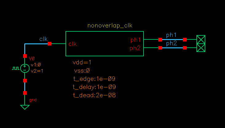
Nonoverlap_clk testbench
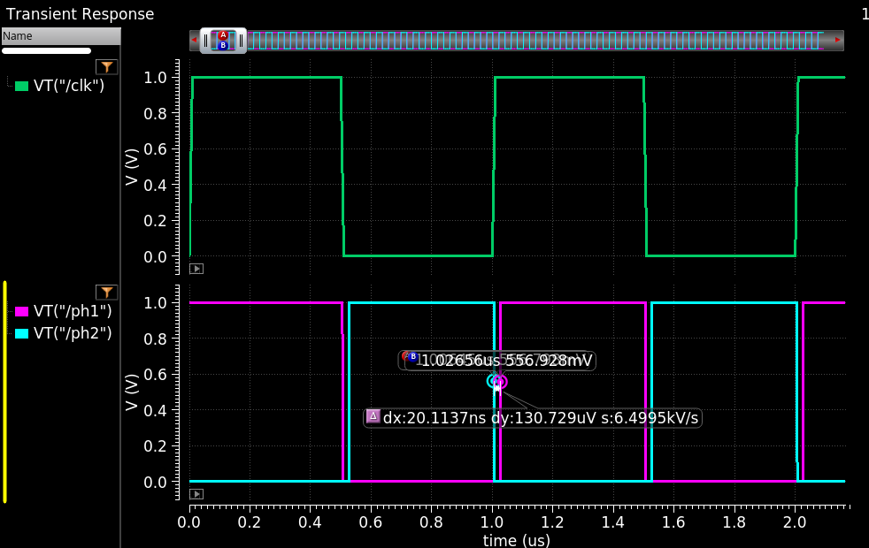
Nonoverlap_clk simulation result
Cell name: nonoverlap_clk
Model type: Verilog-A
1// Non-overlap clock generator (same freq as clk)
2// Author: A. Sidun
3// Source: AnalogHub.ie
4
5`include "constants.vams"
6`include "disciplines.vams"
7
8module nonoverlap_clk (clk, ph1, ph2);
9    input clk;
10    output ph1, ph2;
11    electrical clk, ph1, ph2;
12
13    parameter real vdd = 5.0;		// define clock high
14    parameter real vss = 0.0;		// define clock low
15    parameter real t_edge = 1e-9;	// rising/falling edge of ph1/ph2
16    parameter real t_delay = 1e-9;	// delay from the input clock edge for ph1/ph2
17    parameter real t_dead = 20e-9; 	// dead-time between ph1/ph2
18
19    real delay_ph1;
20    real delay_ph2;
21    real d_ph1;
22    real d_ph2;
23
24analog begin
25@(initial_step) begin
26    d_ph1 = 1;
27    d_ph2 = 0;
28    end
29
30@(cross(V(clk)-vdd/2, +1)) begin	//rising edge of clk
31        d_ph1 = 1;
32        d_ph2 = 0;
33		delay_ph1 = t_delay + t_dead;
34		delay_ph2 = t_delay;
35end
36
37@(cross(V(clk)-vdd/2, -1)) begin	//falling edge of clk
38        d_ph1 = 0;
39        d_ph2 = 1;
40		delay_ph1 = t_delay;
41		delay_ph2 = t_delay + t_dead;
42end
43
44V(ph1) <+ vdd*transition(d_ph1,delay_ph1,t_edge) + vss*transition(d_ph2,delay_ph1,t_edge);
45V(ph2) <+ vdd*transition(d_ph2,delay_ph2,t_edge) + vss*transition(d_ph1,delay_ph2,t_edge);
46
47end //analog begin
48endmodule
Non-overlapping clock generator with 2 phases
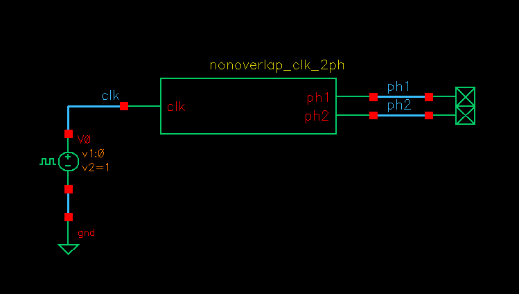
2-phases nonoverlap_clk testbench
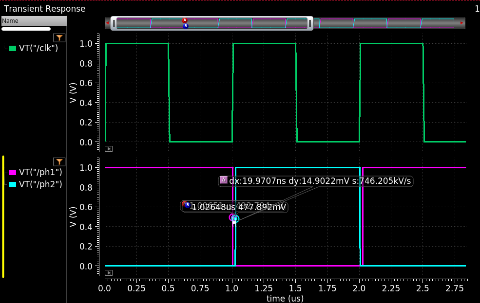
2-phases nonoverlap_clk simulation result
Cell name: nonoverlap_clk_2ph
Model type: Verilog-A
1// Non-overlap clock generator (frequency-divided)
2// Author: A. Sidun
3// Source: AnalogHub.ie
4
5`include "constants.vams"
6`include "disciplines.vams"
7
8module nonoverlap_clk_2ph (clk, ph1, ph2);
9    input clk;
10    output ph1, ph2;
11    electrical clk, ph1, ph2;
12
13   	parameter real vdd = 5.0;   // define clock high
14    parameter real vss = 0.0;	// define clock low
15	parameter real t_edge = 1e-9;   // rising/falling edge of ph1/ph2
16	parameter real t_delay = 1e-9;  // delay from the input clock edge for ph1/ph2
17    parameter real t_dead = 20e-9;  // dead-time between ph1/ph2
18
19    real delay_ph1;
20    real delay_ph2;
21    real d_ph1;
22    real d_ph2;
23    integer counter_ph1=0;
24
25analog begin
26@(initial_step) begin
27    d_ph1 = 1;
28    d_ph2 = 0;
29    end
30
31
32@(cross(V(clk)-vdd/2, +1)) begin	//rising edge of clk
33        counter_ph1 = counter_ph1 + 1; // count rising edges
34		$display("Rising edge number: %d", counter_ph1);
35        case(counter_ph1)
36        1: begin
37            d_ph1 = 1;
38            d_ph2 = 0;
39            delay_ph1 = t_delay + t_dead;
40		    delay_ph2 = t_delay;
41        end
42        2: begin
43            d_ph1 = 0;
44            d_ph2 = 1;
45            delay_ph1 = t_delay;
46		    delay_ph2 = t_delay + t_dead;
47            counter_ph1 = 0;    // reset counter
48        end
49endcase
50end
51
52
53/*@(cross(V(clk)-vdd/2, -1)) begin	//falling edge of clk
54        d_ph1 = 0;
55        d_ph2 = 1;
56		delay_ph1 = t_delay;
57		delay_ph2 = t_delay + t_dead;
58end */
59
60V(ph1) <+ vdd*transition(d_ph1,delay_ph1,t_edge) + vss*transition(d_ph2,delay_ph1,t_edge);
61V(ph2) <+ vdd*transition(d_ph2,delay_ph2,t_edge) + vss*transition(d_ph1,delay_ph2,t_edge);
62
63end //analog begin
64endmodule
Non-overlapping clock generator with 4 phases
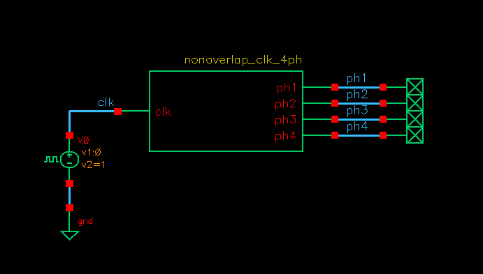
4-phases nonoverlap_clk testbench
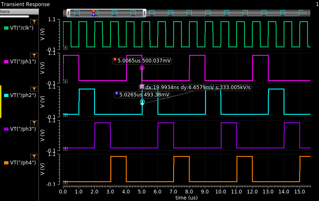
4-phases nonoverlap_clk simulation result
Cell name: nonoverlap_clk_4ph
Model type: Verilog-A
1// 4-phases non-overlap clock generator
2// Author: A. Sidun
3// Source: AnalogHub.ie
4
5//               ____      ____      ____      ____      ____      ____
6// CLK      ____|    |____|    |____|    |____|    |____|    |____|    |____
7//               _________                               _________
8// PH1      ____|         |_____________________________|         |_______________
9//                         _________                               _________
10// PH2      ______________|         |_____________________________|         |_______________
11//                                   _________                               _________
12// PH3      ________________________|         |_____________________________|         |_______________
13//                                             _________                               _________
14// PH4      __________________________________|         |_____________________________|         |_______________
15
16// Non-overlap clock generator (frequency-divided)
17
18`include "constants.vams"
19`include "disciplines.vams"
20
21module nonoverlap_clk_4ph (clk, ph1, ph2, ph3, ph4);
22    input clk;
23    output ph1, ph2, ph3, ph4;
24    electrical clk, ph1, ph2, ph3, ph4;
25
26   	parameter real vdd = 1.0;   // define clock high
27    parameter real vss = 0.0;	// define clock low
28	parameter real t_edge = 1e-9;   // rising/falling edge of ph1/ph2
29	parameter real t_delay = 1e-9;  // delay from the input clock edge for ph1/ph2/ph3/ph4
30    parameter real t_dead = 20e-9;  // dead-time between ph1/ph2/ph3/ph4
31
32    real delay_ph1;
33    real delay_ph2;
34    real delay_ph3;
35    real delay_ph4;
36    real bit_ph1;
37    real bit_ph2;
38    real bit_ph3;
39    real bit_ph4;
40    integer clk_edge_count=0;   // clock rising edge counter
41
42analog begin
43@(initial_step) begin
44    bit_ph1 = 0;
45    bit_ph2 = 0;
46    bit_ph3 = 0;
47    bit_ph4 = 0;
48    end
49
50
51@(cross(V(clk)-vdd/2, +1)) begin	//rising edge of clk
52        clk_edge_count = clk_edge_count + 1; // count rising edges
53		//$display("Rising edge number: %d", clk_edge_count);
54        case(clk_edge_count)
55        1: begin
56            bit_ph1 = 1;
57            bit_ph2 = 0;
58            bit_ph3 = 0;
59            bit_ph4 = 0;
60			delay_ph4 = t_delay;
61            delay_ph1 = t_delay + t_dead;
62        end
63        2: begin
64            bit_ph1 = 0;
65            bit_ph2 = 1;
66            bit_ph3 = 0;
67            bit_ph4 = 0;
68			delay_ph1 = t_delay;
69		    delay_ph2 = t_delay + t_dead;
70
71        end
72        3: begin
73            bit_ph1 = 0;
74            bit_ph2 = 0;
75            bit_ph3 = 1;
76            bit_ph4 = 0;
77			delay_ph2 = t_delay;
78			delay_ph3 = t_delay + t_dead;
79
80        end
81        4: begin
82            bit_ph1 = 0;
83            bit_ph2 = 0;
84            bit_ph3 = 0;
85            bit_ph4 = 1;
86			delay_ph3 = t_delay;
87			delay_ph4 = t_delay + t_dead;
88            clk_edge_count = 0;    // reset counter
89        end
90endcase
91end
92
93V(ph1) <+ vdd*transition(bit_ph1,delay_ph1,t_edge) + vss*transition(bit_ph2,delay_ph1,t_edge);
94V(ph2) <+ vdd*transition(bit_ph2,delay_ph2,t_edge) + vss*transition(bit_ph1,delay_ph2,t_edge);
95V(ph3) <+ vdd*transition(bit_ph3,delay_ph3,t_edge) + vss*transition(bit_ph3,delay_ph3,t_edge);
96V(ph4) <+ vdd*transition(bit_ph4,delay_ph4,t_edge) + vss*transition(bit_ph4,delay_ph4,t_edge);
97
98end //analog begin
99endmodule