Binary Counter Model Verilog-A
This article contains Verilog-A model for a binary counter, which counts up or down at the edge of the clock, when en is high.
Usage:
- Create a new cell in Library Manager named counter and select cell type Verilog A;
- Copy and paste the code provided;
- Specify bits variable to define the number of output bits;
- Specify start_code variable to be the start code of the counter;
- Specify count_up variable to be 1 for increasing or 0 for decresing counting;
- Specify step_size variable to be the step size of the counter (increment);
- Specify vth_clk variable to be threshold volatge of the clock signal;
- Specify vtol and ttol variables as signal and time tolerance to the clock signal;
- Specify vdd variable to be the output voltage of the counter;
- Specify t_edge and t_delay variables to be the rising/falling time and delay of the output waveform;
- Perform Check and Save;
- A cell symbol will be created;
- Instantiate counter cell into your design;
- Perform Check and Save and run the simulation.

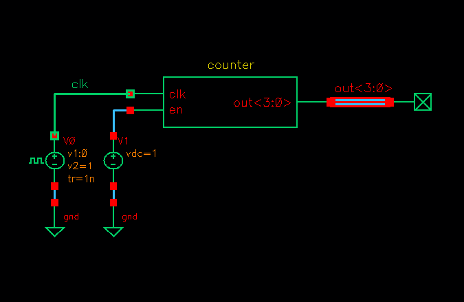
Counter testbench

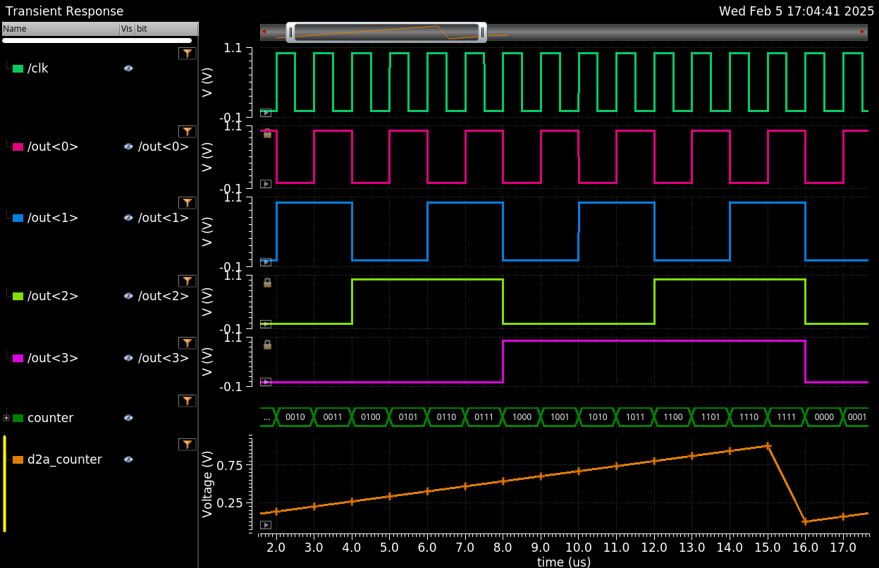
Counter model simulation result
Cell name: counter
Model type: Verilog-A
1// Verilog-A model for Binary Counter
2// Source: AnalogHub.ie
3// Author: A. Sidun
4// Reference: A. Beckett
5
6`include "constants.vams"
7`include "disciplines.vams"
8`define bits 4
9
10module counter (clk,en,out);
11input clk, en;
12output [`bits-1 :0] out;
13electrical clk, en;
14electrical  [`bits-1 :0] out;
15
16parameter integer start_code = 0 from [0:(1<<`bits)-1];   // Start code for the counter
17parameter integer count_up = 1 from [0:1];         // Set 1 for increasing or 0 for decreasing
18parameter integer step_size = 1;              // Step size for the counter
19parameter real vth_clk = 0.5;               // Clock threshold
20parameter real vtol = 0;                  // Signal tolerance on the clk
21parameter real ttol = 0;                  // Time tolerance on the clk
22parameter real vdd = 1.0;
23parameter real vth = 1;
24parameter real vss = 0;
25parameter real t_delay = 30p;               // Delay time for the output waveform
26parameter real t_edge = 30p;               // Rising/falling times of the output waveform
27integer outval;                      // Internal counter
28
29analog begin
30  @(initial_step("static","ac")) outval = start_code;
31  @(cross(V(clk)-vth_clk,1,vtol,ttol)) begin
32    if (V(en)<vth) outval=0.0;
33    else outval = (outval +(+count_up- !count_up)*step_size)%(1<<`bits);
34  end
35  generate j (`bits-1 , 0) begin
36    V(out[j]) <+ transition (!(!(outval &(1<<j)))*vdd+!(outval&(1<<j))*vss,t_delay,t_edge,t_edge);
37  end
38end
39endmodule