Low-pass filter model
This article contains Verilog-A model for a low-pass filter. This model supports two types of filters - 1st-order and 2nd-order.
Usage:
- Create a new cell in Library Manager named LPF and select cell type Verilog A;
- Copy and paste the code provided;
- Specify Cutoff_frequency variable to be -3dB frequency;
- Specify Filter_Order variable to be 1 if you want -20dB/dec or 2 if you want -40dB/dec ;
- Perform Check and Save;
- A cell symbol will be created;
- Instantiate LPF cell into your design;
- Perform Check and Save and run the simulation.

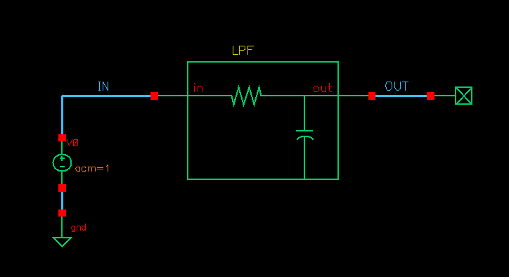
LPF model testbench

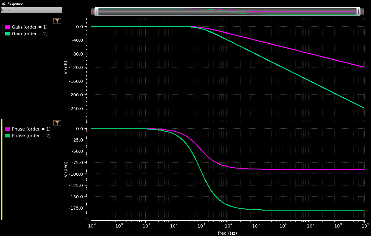
LPF model simulation result (Filter_Order = 1 - purple, Filter_Order = 2 - green)
Cell name: LPF
Model type: Verilog-A
1
2// Low Pass filter model based on -3dB frequency definition
3// Author: A. Sidun
4// Source: AnalogHub.ie
5
6`include "constants.vams"
7`include "disciplines.vams"
8
9module LPF(in, out);
10electrical in, out;
11parameter real Cutoff_frequency = 10k;      // -3dB frequency
12parameter real Filter_Order = 1;            // 1 for 20dB/dec, 2 for 40dB/dec
13
14analog begin
15case (Filter_Order)
161: begin    // First Order LPF (-20dB/dec)
17	V(out) <+ laplace_nd(V(in),{2*`M_PI*Cutoff_frequency},{2*`M_PI*Cutoff_frequency, 1});
18	V(out) <+ laplace_nd(V(in),{2*`M_PI*Cutoff_frequency},{2*`M_PI*Cutoff_frequency, 1});
19    end
20
212: begin    // Second Order LPF (-40dB/dec)
22	V(out) <+ laplace_nd(V(in),{(2*`M_PI*Cutoff_frequency)**2},{(2*`M_PI*Cutoff_frequency)**2, 4*`M_PI*Cutoff_frequency,1});
23    end
24endcase
25end
26endmodule